Wire Settings
This page displays when the user selects the Wire Settings option in the Options dialog. It lets the user set the appearance of wires in drawings.
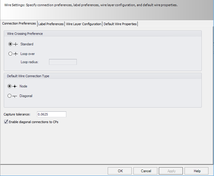
Connection Preferences Tab
| Setting | Description |
|---|---|
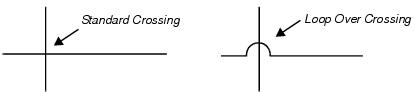
| Wire Crossing Preferences | Determines how a wire will appear when it crosses another wire without connecting. If you select Loop Over, the Loop Over Radius field becomes active, allowing you to enter a radius value for the loop. |
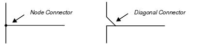
| Default Wire Connection Type | Determines how the connection between two wires will appear by default. Choose Node (connection point) or Diagonal . |
| Capture Tolerance | Determines the radius distance from the end of the two links, so that if a wire gets close to a connection point without being exactly on grid, the software will still treat it as a connection. |
| Enable diagonal connections to CPs | Enable this check box to diagonally draw additional wire segments into a connection point. The first connection drawn is always drawn straight in horizontally or vertically. Additional connections will automatically be routed so that the wires are offset from the initial horizontal or vertical segment and then automatically routed into the connection point at an angle. |
Label Preferences Tab
This tab allows you to format wire labels (wire numbers).

| Setting | Description |
|---|---|
| Enable in Wire number dialog |
Installation & Location - When selected, the installation and location fields will be enabled in the wire number (manual and automatic) dialog. This forces any tags that are entered to be unique for the entire project. Installation only - When selected, only the installation field will be enabled in the wire number (manual and automatic) dialog. |
| Enable in wire link dialog |
Installation & Location - When selected, the installation and location fields will be enabled in the wire link (manual and automatic) dialog. This forces any tags that are entered to be unique for the entire project. Installation only - When selected, only the installation field will be enabled in the wire link (manual and automatic) dialog. |
| Enable duplicate label checking between modes | When selected, the software will allow duplicate wire labels even if the drawings have different drawing modes (schematic, pneumatic, etc.). |
| Consider Installation, Location & Tag | When selected, the installation and location of the wire will be considered part of the wire tag (even though it may not be displayed). This means you could have two wires with the same number in different installations or locations and they would not be considered duplicates because the different installation or location in the tag makes each one unique. |
| Wire Label Display | This field determines the properties of the wire that will be displayed in the drawing. To change the entry, select the Edit button. The Wire Label Display dialog displays allowing you to select the wire properties that will be displayed in the drawing and configure how they will appear. You can combine other elements with the wire tag (wire number) to create a more complex wire ID. |
| Specify tag formats for different types of connections |
Four types of wire labels can be formatted: For each format type, the dialog shows the name of the profile that the format is currently based on (default, etc.) If you wish to change this setting, select the Edit button for that field. The Wire Tag Format dialog displays allowing you to configure the format of the wire label. |
Wire Layer Configuration Tab
This tab is for making settings for drawing wires on two or more different levels. You can assign different wire properties such as gauge, color and voltage to different levels. This will, for example, allow you to draw power wires on one layer and signal wires on another level. The appropriate properties are then automatically assigned to each wire type.

| Setting | Description |
|---|---|
| Allow Multiple Wires Per Mode | If this option is set to On the software will allow the user to define different types of logic line layers for each drawing mode. If this option is set to Off the software will only permit the user to define one layer for logic lines for each mode. |
| Import Layers | Select this button to open a file browser dialog and select a .DWG or .DXF file. After the file is opened the software will extract all the layer names used in the drawing and list them in the layer configuration dialog. |
| New Layer | Select this button to enter the name of a new layer and add it to the list. |
| Delete Layer | If the user selects this button the currently selected layer will be deleted. |
| Drawing Mode | |
| Use | The Use column allows you to assign a description to the logic line layer. When you place the cursor in that column a drop-down list will appear that lists every use that has already been defined. |

The More Properties button will display a dialog that lists the other ten user-definable attributes.
Select OK to load the layer configuration settings.
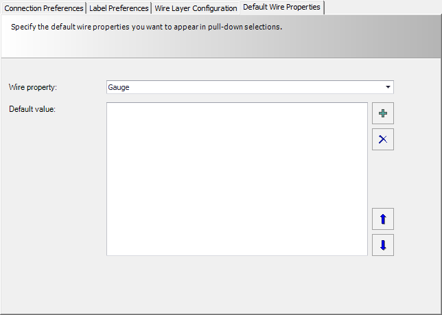
Default Wire Properties Tab
This tab sets the values that are prompted when setting wire properties in a drawing or in the Wiring Manager.
| Setting | Description |
|---|---|
| Wire Property | Select a property from the drop down list. The available selections are Gauge, Color, Type, Voltage and Current. |
| New Value | Click the + button to enter new value. You will be prompted with the Add dialog where you can enter the value. This value will then appear in the Default Value field. You can add more values as needed. |
| Move Values | You can set the order of the default values by selecting a value in the Default Value field and then selecting the up or down arrow button to move it up or down the list. |
| Delete | You can delete a value by selecting it and then selecting the X button. |